
How to Design a Foundation Pit Monitoring System: From Inclinometers and Settlement Monitoring to Automation and Risk Alerts
As urban underground development continues to expand, deep excavations have become increasingly common in modern construction. Metro stations, underground parking facilities, high-rise building foundations, and utility tunnels all require careful excavation and ground stability management.
The risks associated with excavation are not limited to the soil itself. They are also influenced by groundwater conditions, retaining structure forces, surrounding buildings, adjacent infrastructure, and changes in construction activities.
Excessive retaining wall displacement, accelerating ground settlement, abnormal groundwater levels, or unexpected changes in support forces can affect excavation stability and potentially damage nearby roads, utilities, and buildings.
Therefore, an effective foundation pit monitoring system involves much more than installing instruments and collecting readings periodically. It requires an integrated approach covering field sensing, data acquisition, remote transmission, data analysis, and risk alerts.
So, how should an automated foundation pit monitoring system be designed?
1. What Should a Foundation Pit Monitoring System Measure?
The first question is straightforward: which parameters can help engineers identify changing site conditions and potential risks?
Monitoring requirements vary according to excavation depth, geological conditions, support systems, surrounding infrastructure, and the project’s risk profile. The actual monitoring plan should follow the engineering design, applicable standards, and project-specific requirements.
Common monitoring parameters include the following.
1.1 Horizontal Displacement: Why Is Inclinometer Monitoring Important?
Excavation changes the stress conditions around the retaining structure. Soil pressure, groundwater pressure, and construction activities can cause horizontal displacement of retaining walls or surrounding ground.
Inclinometer monitoring helps engineers understand how lateral displacement varies with depth, identify zones of concentrated deformation, and observe whether displacement is continuing to develop.
Common approaches include:
- Manual inclinometer monitoring: Technicians visit the site and take measurements using portable instruments.
- Automated inclinometer monitoring: Suitable automated instruments and compatible acquisition systems collect measurements according to a defined schedule.
- Higher-frequency monitoring: Monitoring frequency may be increased during critical construction stages or when conditions require closer observation.
Automated inclinometer monitoring is not simply a matter of replacing a portable instrument with a data logger. Measurement principles, sensor design, installation requirements, calibration, and data processing may differ significantly.
The measurement method should therefore be selected before choosing the acquisition equipment.
1.2 Ground Settlement and Settlement of Adjacent Buildings
Excavation can cause soil stress redistribution and groundwater changes, potentially resulting in settlement of nearby ground surfaces, roads, utilities, and buildings.
Settlement monitoring helps engineers determine whether:
- Ground settlement is continuing to develop.
- The affected area is expanding.
- Nearby buildings are experiencing abnormal deformation.
- Significant changes correspond to particular construction stages.
Traditional settlement monitoring often uses precise leveling and other surveying methods. Automated surveying systems may be appropriate where higher monitoring frequency or reduced routine site visits are required.
However, automated solutions must account for reference stability, instrument installation, environmental effects, and data quality. The ability to transmit measurements remotely does not, by itself, guarantee reliable settlement measurements.
1.3 Support Axial Force and Structural Loading
For excavations using internal struts, anchors, or other support systems, changes in structural loading are important monitoring indicators.
Depending on the engineering design, suitable instruments may include load cells, strain gauges, and axial force monitoring devices.
For applications using vibrating wire sensors, vibrating wire load cells and strain gauges can convert mechanical changes into corresponding changes in vibrating wire frequency. Compatible data acquisition equipment can measure these signals and calculate engineering values.
The objective is not simply to know the force at a particular moment. Engineers also need to understand how the force changes during excavation, support installation, support removal, and other construction activities.
1.4 Groundwater Level and Pore Water Pressure
Groundwater changes can affect effective soil stress, excavation stability, and deformation of surrounding ground.
Depending on site conditions, monitoring may include:
- Groundwater level.
- Pore water pressure.
- Groundwater response during dewatering.
- Relationships between groundwater changes, ground settlement, and retaining wall displacement.
Suitable instruments may include groundwater level sensors and pore water pressure transducers.
An automated monitoring platform can bring these measurements together with displacement and structural loading data to support more comprehensive analysis.
1.5 Why Should Monitoring Parameters Be Combined?
A single parameter rarely provides a complete picture of excavation conditions.
For example, increasing retaining wall displacement may coincide with changes in support forces. Groundwater drawdown may also be associated with surrounding ground settlement.
A practical monitoring plan should therefore combine parameters according to the project’s risk mechanisms rather than simply maximizing the number of installed sensors.
2. Manual Monitoring vs. Automated Monitoring
Manual monitoring remains valuable in many engineering projects. Automated monitoring is not intended to replace every manual measurement, but to complement it where higher measurement frequency, faster access to data, or fewer routine site visits are beneficial.
| Aspect | Manual Monitoring | Automated Monitoring |
| Data collection | Periodic measurements by personnel | Scheduled automatic acquisition, depending on the equipment |
| Monitoring frequency | Influenced by staffing and site access | Configurable according to project requirements |
| Data transmission | May require manual recording and uploading | Can transmit data through wired or wireless networks |
| Response to anomalies | Depends on measurement, review, and reporting procedures | Can generate alerts when configured rules are triggered |
| Site workload | Requires personnel for routine measurements | Can reduce repetitive fieldwork |
| Initial investment | Can be relatively flexible | May require additional sensors, acquisition units, communications, and software |
| Data quality control | Depends on operator procedures, verification, and review | Still requires calibration, validation, anomaly detection, and maintenance |
Automation does not automatically mean higher measurement accuracy.
Poor sensor installation, unstable reference points, unreliable communications, and incorrect configuration can all compromise automated measurements.
The goal is not simply to connect instruments to a network. It is to build a reliable, verifiable, and maintainable data chain.
3. What Are the Main Components of an Automated Foundation Pit Monitoring System?
A typical system can be divided into five layers.
Layer 1: Sensors and Measurement Instruments
Sensors provide the measurement data on which the entire system depends.
Depending on the monitoring plan, instruments may include:
- Inclinometers or automated inclinometer systems.
- Settlement monitoring instruments.
- Vibrating wire strain gauges, load cells, and axial force sensors.
- Vibrating wire pore water pressure transducers.
- Groundwater level sensors.
- Temperature, humidity, and other environmental sensors.
Different sensors use different measurement principles and output interfaces.
Vibrating wire sensors typically provide signals associated with frequency or period. Some digital sensors communicate through RS485 using protocols such as Modbus. Other instruments may use analog signals, pulses, or proprietary interfaces.
Before selecting a data acquisition device, engineers should verify sensor type, output format, power requirements, communication protocol, and engineering-unit conversion requirements.
Layer 2: Data Acquisition Units and RTUs
After measurements are taken, compatible data acquisition equipment collects the signals and performs the configured processing.
For foundation pit projects using vibrating wire sensors, vibrating wire data loggers or hybrid acquisition RTUs may support functions such as:
- Multi-channel vibrating wire acquisition.
- Temperature measurement.
- Frequency measurement and digital filtering.
- Engineering-unit conversion based on configured parameters.
- Communication with compatible digital sensors.
- Local data storage and communication management.
- Scheduled reporting and configured alarm functions.
For example, a vibrating wire load cell produces a measurement signal related to its resonant frequency. After acquiring frequency and temperature data, the system can calculate engineering values using the sensor’s calibration coefficients and applicable conversion formula.
The calculation parameters are sensor-specific. Initial readings, calibration coefficients, temperature compensation parameters, and units must be configured according to the sensor documentation and project requirements.
A single conversion formula should not be assumed to apply to every sensor.
Layer 3: Communication Networks
Acquired data must be transmitted to the monitoring platform.
Common communication options include:
- RS485: Wired communication between field devices.
- 4G: Remote transmission where cellular coverage is available.
- Ethernet: Wired networking where suitable infrastructure exists.
- Other wireless technologies: Selected according to site conditions and system requirements.
A distributed foundation pit monitoring system may combine local wired connections with wireless communication to a remote server.
For example, field sensors can connect to an acquisition unit, while a 4G-enabled RTU transmits the collected data to a remote monitoring platform.
It is important to distinguish between RS485, which is a physical communication interface, and Modbus, which is a communication protocol. Successful integration also depends on matching baud rates, parity settings, device addresses, register definitions, and protocol implementations.
Wireless signal quality should also be evaluated before deployment. Underground spaces, dense urban environments, and metal structures can affect cellular connectivity.
Layer 4: Monitoring Platform and Data Management
The monitoring platform receives, stores, displays, and analyzes field data.
Typical functions include:
- Monitoring point and sensor management.
- Real-time and historical data access.
- Trend charts and reports.
- Device and monitoring-point status management.
- Threshold configuration and alarm records.
- Centralized management of multiple projects and devices.
- Data export and engineering record management.
The platform should do more than display the latest measurement. It should retain historical records and distinguish measurement time, receipt time, device status, and data-quality conditions.
Correlating monitoring data with construction progress is particularly important.
Measurements taken before excavation, during excavation, after support installation, and during dewatering may have different engineering significance. Combining monitoring data with construction logs, excavation depth, and support conditions helps engineers investigate changes more effectively.
Layer 5: Risk Alerts and Engineering Response
The ultimate objective of a monitoring system is not to produce attractive charts. It is to help engineers identify abnormal conditions in time and support appropriate engineering decisions.
A typical alert workflow includes:
Data acquisition → Data quality checks → Threshold evaluation → Alert notification → Engineering review → Site inspection and response → Verification and documentation.
Automated alerts are only one part of risk management. Significant anomalies must be reviewed against site conditions, engineering design requirements, and professional judgment.
4. How Should Sensors and Data Acquisition Equipment Be Selected?
Equipment selection should be based on monitoring requirements rather than channel count, communication options, or price alone.
4.1 Identify Sensor Types and Quantities
Determine which parameters must be monitored, how many monitoring points are required, and which sensor types will be installed.
If a project uses vibrating wire load cells, strain gauges, and pore water pressure transducers, verify that the selected acquisition equipment supports those sensors.
If the system also needs groundwater level sensors, rain gauges, or other RS485 digital instruments, confirm the available digital interface, supported protocols, and data-point capacity.
Vibrating wire channel capacity and digital sensor integration capacity are not the same thing. A device with multiple vibrating wire channels does not necessarily have the same number of RS485 or Modbus channels.
4.2 Verify Measurement Range, Accuracy, and Conversion Parameters
For vibrating wire sensors, consider:
- Frequency or period measurement range.
- Measurement accuracy and resolution.
- Temperature measurement and compensation.
- Sensor calibration parameters.
- Engineering-unit conversion formulas.
- Long-term stability and environmental suitability.
A single accuracy figure in a product brochure is not enough to determine the accuracy of the complete monitoring system.
Final measurement performance also depends on the sensor, installation, calibration, environmental conditions, data processing, and maintenance.
4.3 Define the Acquisition Interval
Not every monitoring point needs to use the same acquisition interval.
During relatively stable construction stages, an interval appropriate to the monitoring plan may be sufficient. During excavation, support changes, dewatering, or other critical activities, the monitoring schedule may need to be adjusted according to the design requirements and risk assessment.
The monitoring plan and applicable standards should determine the required frequency, rather than the equipment’s default settings alone.
4.4 Evaluate Power and Communication Conditions
For long-term unattended operation, evaluate:
- Availability of stable mains power.
- Requirements for solar power and batteries.
- Power consumption of sensors and RTUs.
- 4G coverage and signal stability.
- Local storage capacity during network outages.
- Maintenance and fault-recovery arrangements.
For remote monitoring points with limited power or communication infrastructure, low-power design, scheduled acquisition, sleep management, and local data storage can be especially valuable.
4.5 Check Compatibility and Expansion Capabilities
Engineering projects frequently involve sensors from different manufacturers.
Before deployment, verify communication protocols, data formats, interface definitions, and platform integration requirements.
Support for MQTT, Modbus RTU, or another protocol does not guarantee automatic compatibility with every device using that protocol. Register addresses, data types, byte order, scaling factors, and error handling must also be checked.
5. Why Must Automated Monitoring Account for Network Outages?
Field monitoring systems operate in construction environments where communication networks may be unstable.
If a device continues collecting measurements during a network outage but cannot store them locally, some monitoring records may be lost.
This can compromise the completeness of the data needed to analyze trends.
A robust automated monitoring system should therefore consider Store-and-Forward, a mechanism for storing data locally during communication outages and forwarding it after connectivity is restored.
The basic workflow is:
- The device collects measurements according to its configuration.
- When the network is available, data is uploaded as configured.
- During an outage, measurements are stored locally.
- After communication is restored, unsent historical data is retransmitted.
- The platform checks timestamps, duplicates, and data completeness.
Two concepts must be distinguished:
- Successful acquisition: The device has measured and stored the data.
- Successful upload: The remote platform has received and acknowledged the data.
If a system only records upload status without retaining local acquisition records, it may be difficult to determine whether measurements were actually collected during the outage.
Store-and-forward should also be complemented by device health monitoring. Power status, communication status, sensor anomalies, storage capacity, and data freshness should be monitored where supported.
For critical monitoring points, the system design should specify the required outage tolerance, local storage capacity, retransmission strategy, and data integrity checks.
6. Why Should Foundation Pit Risk Alerts Go Beyond a Single Threshold?
Many monitoring systems use upper and lower limits to trigger alarms when a measurement exceeds a configured threshold.
This approach is simple and useful, but actual engineering risks can be more complex than a single threshold can represent.
6.1 Absolute-Value Alerts
An alert can be triggered when a monitoring parameter exceeds a control value defined by the project design or monitoring plan.
This is a fundamental approach to automated alerting.
The actual control values, alert levels, and response procedures must be established according to the engineering documents, monitoring plan, and applicable standards. Values from another project should not be copied without assessment.
6.2 Rate-of-Change Alerts
In some cases, a measurement may remain below its control limit while changing significantly faster than before.
For example, retaining wall displacement may increase over several acquisition cycles, or support force may fluctuate after a change in construction conditions.
Monitoring the rate of change can therefore provide additional information beyond absolute values.
However, rate-of-change thresholds must be designed with consideration for the monitored parameter, measurement noise, acquisition interval, and site conditions.
6.3 Multi-Parameter Analysis
Where displacement, support force, and groundwater are monitored in the same area, their trends can be analyzed together.
For example, increasing retaining wall displacement accompanied by groundwater changes and variations in support force may warrant further investigation alongside construction records.
However, simultaneous changes do not automatically prove a specific failure mechanism. The system should provide reliable measurements and useful indications, while engineering interpretation must consider geology, construction conditions, and professional analysis.
6.4 Connect Alerts to an Action Workflow
A useful alert system should do more than send a notification to a mobile phone.
A more complete process includes:
- Detecting abnormal data.
- Generating alerts according to project-defined rules.
- Recording the time, monitoring point, and relevant measurements.
- Notifying designated personnel.
- Reviewing the data and checking site conditions.
- Carrying out inspections, verification, or other required actions.
- Recording the response and its outcome.
Sensor failures, communication outages, and power problems may also cause abnormal or missing data. These conditions should be distinguished from alerts indicating actual engineering deformation.
7. How Can a Vibrating Wire Hybrid Acquisition RTU Support Foundation Pit Monitoring?
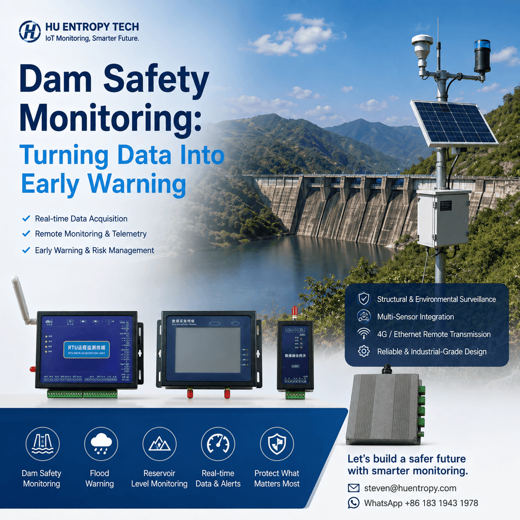
For foundation pit projects using vibrating wire sensors, a vibrating wire data logger or hybrid acquisition RTU can form part of the data chain between field instruments and the remote monitoring platform.
A suitable RTU with multi-channel vibrating wire acquisition, an RS485 interface, and 4G communication may support the following functions, depending on its specifications and configuration.
1. Multi-channel vibrating wire acquisition
Measure compatible vibrating wire sensors, such as load cells, strain gauges, and pore water pressure transducers, and acquire associated temperature data where supported.
2. Local data processing
Apply configured sensor parameters and conversion formulas to process measurements and calculate engineering values within the device’s supported capabilities.
3. Integration with compatible digital sensors
Connect digital sensors through RS485 when their communication protocols and data formats are supported. Actual integration capacity depends on the device interface, protocol implementation, and project configuration.
4. Remote data transmission
Transmit field data to a monitoring platform through 4G or another supported communication method, reducing the need for routine manual data collection.
5. Local storage and abnormal-condition reporting
Where supported, local storage, store-and-forward, and configured threshold alerts can help improve data continuity and remote monitoring response.
It is important to recognize that a vibrating wire hybrid acquisition RTU cannot replace every foundation pit measurement instrument. Traditional inclinometer surveys and precise leveling, for example, may require dedicated instruments and separate data-processing workflows.
The appropriate architecture is not to make one device perform every measurement task. It is to select suitable instruments for each monitoring requirement and integrate their data through a coordinated monitoring platform.
8. How to Implement a Practical Foundation Pit Monitoring System
A real project can be developed through the following steps.
Step 1: Define Engineering Risks and Monitoring Requirements
Review excavation depth, geological conditions, support systems, nearby buildings, and underground utilities. Determine the required monitoring parameters according to the design and monitoring plan.
Step 2: Develop the Monitoring Point Layout
Define the location of each monitoring point, the monitored parameter, instrument type, measurement range, and installation requirements.
The layout should support engineering decisions rather than simply maximize the number of devices.
Step 3: Select Instruments and Acquisition Equipment
Choose equipment according to sensor principles, interfaces, channel capacity, accuracy, power requirements, communication options, and environmental conditions.
Where multiple sensor brands are involved, verify compatibility before deployment.
Step 4: Design the Power and Communication System
Select wired, 4G, or other communication methods based on site conditions. Evaluate power stability, signal coverage, storage capacity, and maintenance requirements.
Step 5: Install, Commission, and Establish Baseline Measurements
After installation, verify sensor connections, monitoring point IDs, configuration parameters, acquisition intervals, communication status, and platform data.
Establishing reliable baseline measurements is particularly important. Without trustworthy initial readings, subsequent changes may be difficult to interpret correctly.
Step 6: Establish Data Quality Controls
Define checks for missing data, abnormal jumps, stale measurements, sensor faults, and communication failures.
An automated system must distinguish between a measurement that has not changed and a measurement that has not been updated.
Step 7: Configure Alerts and Response Procedures
Set thresholds, notification recipients, and response requirements according to the monitoring plan. Clarify who reviews alerts, who inspects the site, and who records the results.
Step 8: Maintain and Verify the System
Regularly inspect power supplies, communication links, sensor conditions, and measurement results. Significant anomalies should be verified through repeat measurements or independent methods where appropriate.
Automated monitoring does not end when installation is complete. It is an ongoing process of operation, verification, maintenance, and improvement.
9. Where Is Foundation Pit Monitoring Heading?
As engineering IoT technologies develop, foundation pit monitoring is moving toward remote operation, multi-parameter integration, and more coordinated data management.
Several trends deserve attention.
1. Combining automated monitoring with manual verification
Automation can increase measurement frequency for suitable monitoring tasks, while manual methods remain important for precision surveys and measurements requiring specific procedures.
2. Integrating multiple sensor types
Bringing vibrating wire, digital, and other compatible sensor data into a common platform can provide engineers with a more complete view of site conditions.
3. Moving data processing closer to the field
Edge computing can support local data processing, engineering-unit conversion, and preliminary anomaly checks. This can reduce unnecessary data transmission and improve responsiveness for supported functions.
4. Moving from fixed thresholds toward trend analysis
With reliable data, systems can analyze rates of change, historical trends, and relationships among multiple parameters. However, algorithms must be validated for the engineering application. Model outputs should not be treated as definitive safety conclusions.
5. Improving end-to-end data reliability
Local storage, store-and-forward, device health monitoring, data quality checks, and closed-loop alert management are becoming important components of automated monitoring system design.
Conclusion
The main challenge in foundation pit monitoring is not simply choosing an inclinometer, settlement instrument, or data acquisition device. It is building a reliable, continuous, and traceable monitoring system that supports engineering decisions.
Each measurement method—from inclinometer and settlement monitoring to support force and groundwater monitoring—has its own capabilities and limitations.
By identifying project risks first and then selecting appropriate sensors, acquisition equipment, communication methods, and analytical tools, engineers can make monitoring data more useful for construction management and risk control.
For projects requiring remote automation, vibrating wire acquisition equipment, hybrid acquisition RTUs, 4G communication, edge processing, and store-and-forward mechanisms can be important components of the system architecture.
Ultimately, system reliability depends on sound engineering design, correct equipment selection, proper installation and commissioning, trustworthy data, and timely on-site response.
A good foundation pit monitoring system does more than collect data. It helps ensure that data is trustworthy, anomalies are detectable, events are traceable, and engineering decisions are supported by evidence.
Hu Entropy Tech focuses on data acquisition and industrial IoT solutions for engineering monitoring applications. To learn more about our products and technical capabilities, visit https://huentropytech.com/.
#FoundationPitMonitoring #GeotechnicalMonitoring #VibratingWire #DataAcquisition #RTU #IndustrialIoT #StructuralHealthMonitoring #ExcavationMonitoring #EngineeringMonitoring
