
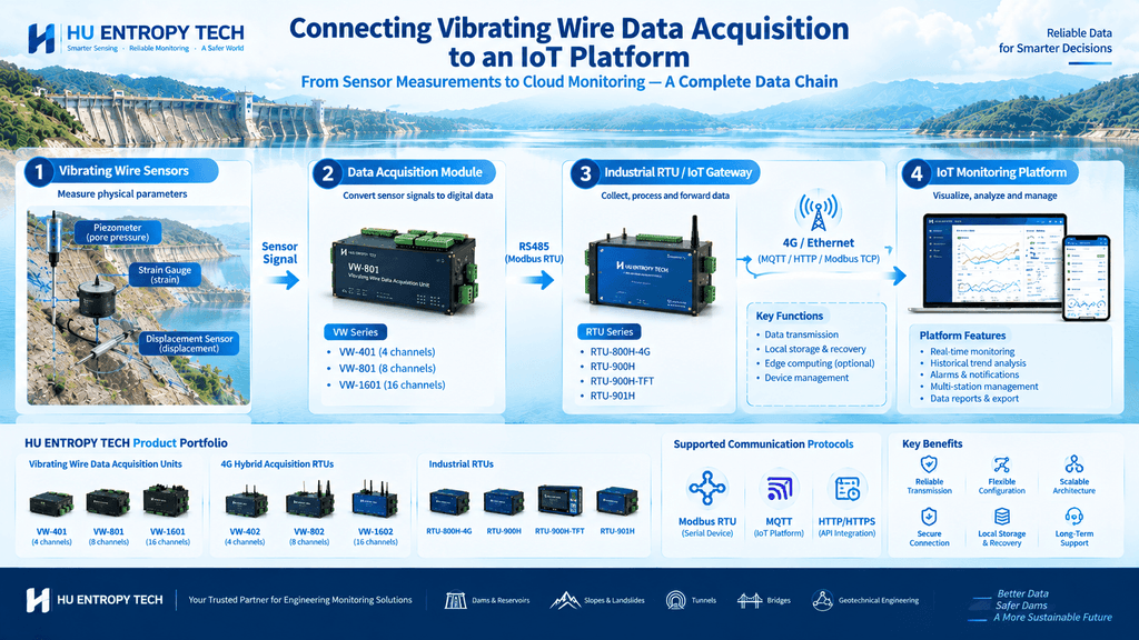
From sensor measurements to cloud-based monitoring: A practical integration guide for engineering monitoring systems.
Vibrating wire sensors are widely used in dam safety monitoring, geotechnical engineering, foundation pits, tunnels, slopes, and structural health monitoring.
But collecting measurements from a sensor is only the first step.
To make those measurements available for remote monitoring, historical analysis, visualization, and alarm management, engineers need to connect the field acquisition equipment to an IoT platform.
This raises several practical questions:
- How does a vibrating wire data acquisition module communicate with an IoT platform?
- Is an industrial RTU or IoT gateway required?
- Which communication protocols should be considered?
- How should measurement data be mapped, transmitted, and displayed?
- What happens when the network connection fails?
In this article, we will walk through the integration process, from the field sensor to the monitoring platform.
1. Understand the Complete System Architecture
Before configuring any equipment, engineers should identify the role of each component.
A typical remote monitoring system includes four main layers.
Layer 1: Field Sensors
Vibrating wire sensors measure physical parameters through changes in their vibration frequency. Depending on the instrument, these measurements may be used to determine pore-water pressure, strain, displacement, or other engineering parameters.
Layer 2: Data Acquisition
A compatible vibrating wire data acquisition module excites and measures the sensor signal, then processes it into usable measurement data.
The acquisition device must support the relevant sensor type and measurement requirements.
Layer 3: Communication and Telemetry
An industrial RTU or IoT gateway can connect the acquisition equipment to the communication network. Depending on the device, it may read data through RS485, support a compatible protocol such as Modbus RTU, and forward measurements over 4G or Ethernet.
Some products integrate acquisition and telemetry functions, eliminating the need for a separate gateway.
Layer 4: IoT Platform
The platform receives the data and makes it available for monitoring dashboards, historical trends, alarm rules, reports, and other application functions.
A common architecture is:
Vibrating Wire Sensor → Data Acquisition Unit → Industrial RTU / IoT Gateway → 4G or Ethernet → IoT Platform
This is a general reference architecture, not a mandatory design. The actual configuration depends on the acquisition device, available interfaces, supported protocols, and platform requirements.
2. Step One: Confirm the Acquisition Module’s Interface
The first technical task is to determine how the vibrating wire acquisition module exposes its measurement data.
For example, an acquisition unit may provide an RS485 interface for communication with an external device.
However, having an RS485 interface does not automatically mean that the module supports every communication protocol. Engineers must verify the actual protocol and configuration requirements in the product documentation.
Check the following:
- Physical interface, such as RS485
- Supported communication protocol
- Device address
- Baud rate and serial communication settings
- Register map or data access method
- Measurement data format
- Supported channel count
- Whether configuration and measurement data use different commands
If Modbus RTU is supported, the RTU or gateway can typically read the relevant registers according to the manufacturer’s register map.
If the device uses a proprietary protocol, the gateway or platform integration may require a compatible driver or custom software.
Important: RS485 is a physical communication interface, while Modbus RTU is a communication protocol. They are related, but they are not the same thing.
Confirming this distinction early can prevent significant integration work later.
3. Step Two: Choose the Right Connection Architecture
There are several ways to connect vibrating wire acquisition equipment to an IoT platform.
Option A: Acquisition Module + Industrial RTU + IoT Platform
This architecture uses a separate RTU or gateway to read data from the acquisition module.
Example:
Vibrating Wire Sensors → Acquisition Unit → RS485 / Modbus RTU → Industrial RTU → 4G / Ethernet → IoT Platform
This arrangement may be suitable when:
- The acquisition unit already exists in the project.
- Remote communication needs to be added.
- Several compatible devices need to be connected to a common gateway.
- The customer already has an RTU-based monitoring architecture.
- The acquisition equipment and communication equipment need to be selected independently.
The RTU’s actual interfaces, protocol support, and data-handling capabilities must match the project requirements.
Option B: Integrated 4G Vibrating Wire Acquisition RTU
In some projects, an integrated device can perform vibrating wire acquisition and provide 4G-oriented remote monitoring functions.
Example:
Vibrating Wire Sensors → Integrated Acquisition RTU → 4G Network → IoT Platform
This architecture may reduce the number of separate devices and simplify installation at remote monitoring stations.
It can be worth evaluating when a project requires both vibrating wire measurement and cellular telemetry.
However, integration does not guarantee compatibility with every IoT platform. The device’s supported communication methods, data formats, and platform interface still need to be confirmed.
Option C: Acquisition Module + Customer-Developed Gateway
Some system integrators prefer to use their own gateway software or industrial computer.
In this case, the gateway reads data from the acquisition module and converts it into the format required by the customer’s platform.
This approach can provide greater control over data processing and system integration, but it may require additional software development, testing, and maintenance.
The best architecture depends on the customer’s existing infrastructure, development resources, deployment scale, and long-term support strategy.
4. Step Three: Select a Communication Protocol for the Platform
The communication protocol determines how data moves between devices and software systems.
Three technologies are particularly relevant to industrial monitoring integrations, although they serve different purposes.
Modbus RTU: Communication with Field Devices
Modbus RTU is commonly used for communication between industrial devices over serial interfaces such as RS485.
When the vibrating wire acquisition unit supports Modbus RTU, a compatible RTU or gateway can read the relevant measurement registers.
The gateway must understand the register addresses, data types, scaling rules, and device communication settings.
Modbus RTU is generally used for communication at the field-device level. It does not, by itself, define how the data is delivered to a cloud platform.
MQTT: Messaging Between Devices and IoT Platforms
MQTT is a lightweight messaging protocol commonly used in IoT systems.
A gateway or RTU that supports MQTT can publish data to a configured MQTT broker, provided that its implementation is compatible with the platform.
A typical data path is:
Acquisition Unit → RTU / Gateway → MQTT Broker → IoT Application
The message may contain device identification, measurement values, timestamps, and status information.
The exact message structure depends on the platform and integration requirements.
For example, an application might define a JSON message containing a device ID, channel ID, measurement value, unit, and timestamp. This is an illustrative format; it is not a universal requirement or a claim about the output format of any particular HU ENTROPY TECH product.
HTTP / HTTPS: Application-Level Data Integration
Some IoT platforms accept data through HTTP-based APIs.
In this architecture, a gateway or application sends measurement records to a defined endpoint using the API’s required format and authentication method.
This approach may be suitable when the customer’s platform already provides an HTTP API, but the selected equipment or gateway must support the required integration method.
Engineering principle: Do not select a protocol simply because it is popular. Select one that is supported by the field equipment, compatible with the platform, and appropriate for the required data flow.
5. Step Four: Map the Measurement Data Correctly
Successful communication does not necessarily mean that the measurement data is correct.
A platform may receive data but display an incorrect value if the register mapping, data format, or conversion formula is wrong.
For each measurement channel, engineers should establish a clear data definition.
| Data field | What to verify |
|---|---|
| Device ID | Unique identification of the acquisition device |
| Channel ID | Which sensor or measurement point the channel represents |
| Raw reading | The value returned by the acquisition device |
| Engineering value | The value derived using the applicable conversion or calibration relationship |
| Unit | For example, kPa, mm, or another unit appropriate to the instrument |
| Timestamp | When the measurement was taken |
| Status | Whether the record is valid, unavailable, or associated with an error |
| Location | The corresponding monitoring point in the project |
Not every acquisition device exposes all these fields directly. Some information may need to be configured in the gateway or platform.
Raw Data vs. Engineering Values
A vibrating wire instrument may provide a frequency-related reading or another device-specific measurement representation.
The final engineering value depends on the sensor’s calibration relationship, reference readings, coefficients, and applicable correction procedures.
For example, a pore-water pressure monitoring application may require the acquisition reading to be converted into pressure units using the sensor’s calibration data.
The conversion method must follow the sensor manufacturer’s documentation and the project’s measurement procedures.
Do not assume that a raw reading can be interpreted directly as pressure, displacement, or strain without the required conversion.
Incorrect scaling or calibration can produce plausible-looking but misleading data.
6. Step Five: Design the Platform’s Data Model
Once the communication and measurement mapping are defined, the platform needs a consistent way to organize the incoming records.
For an engineering monitoring project, the data model should connect each record to the correct device, channel, sensor, and physical monitoring point.
For example, a dam monitoring platform might organize its data as follows:
- Project: Dam A
- Monitoring area: Downstream section
- Monitoring station: Station 03
- Acquisition device: Device 03
- Channel: Channel 05
- Sensor: Piezometer P-05
- Parameter: Pore-water pressure
- Measurement: Value with unit and timestamp
This structure helps engineers identify where a measurement came from and compare readings across different locations.
The platform should also distinguish between:
- The time the measurement was taken
- The time the platform received the record
- The time the record was processed or updated, if relevant
These timestamps may differ when a remote station experiences network delays or forwards locally stored records after reconnecting.
Preserving the original measurement timestamp is especially important for historical trend analysis.
7. Step Six: Plan for Network Interruptions and Data Recovery
Remote monitoring stations may operate in locations with intermittent cellular coverage or unstable network connections.
If the communication link fails, the acquisition device may still be able to measure data, depending on its design and power supply. However, successful recovery depends on where data is stored and whether the system supports retransmission.
For projects requiring data continuity, evaluate whether the acquisition unit, RTU, gateway, or another component supports local data logging and Store-and-Forward.
A typical recovery workflow is:
- The acquisition system collects a measurement.
- The record is stored locally if supported and configured.
- The network connection becomes unavailable.
- The device continues collecting and storing data, subject to its capabilities and available power.
- The network connection is restored.
- Stored records are forwarded to the platform if automatic retransmission is supported.
- The platform checks timestamps and record identifiers to handle delayed or duplicate data appropriately.
Before deployment, verify storage capacity, retention limits, timestamp preservation, retransmission behavior, and duplicate-handling logic.
These functions are model- and configuration-dependent. Local storage should not automatically be assumed to include Store-and-Forward.
For critical monitoring projects, test a real network interruption and recovery scenario before commissioning.
8. Step Seven: Configure Monitoring Dashboards and Alarms
Once the platform receives and correctly interprets the measurement data, engineers can configure the application layer.
Typical functions may include:
- Real-time or latest-value dashboards
- Historical trend charts
- Monitoring-point maps
- Data export and reporting
- Device online/offline status
- Measurement validity indicators
- Configurable threshold alarms
- Notifications to responsible personnel
For example, a dam monitoring dashboard may display pore-water pressure measurements alongside reservoir water levels and other relevant parameters.
This can help engineers interpret changes in context rather than reviewing each measurement independently.
However, alarm rules must be designed according to the project’s engineering requirements. A threshold should not be selected merely because it is easy to configure.
Where appropriate, the system may also distinguish between a measurement alarm and a communication alarm. A sensor reading that exceeds a defined threshold is a different event from a device that stops communicating.
An IoT platform supports engineering decisions; it does not replace the engineering procedures required to assess safety.
9. Security and Reliability: What Should Engineers Check?
Connecting field equipment to an IoT platform introduces communication and cybersecurity considerations.
The specific controls depend on the device, network, and platform architecture, but engineers should evaluate:
- Device authentication and access control
- Secure communication options where supported
- Credential management
- Network segmentation where appropriate
- Configuration access restrictions
- Firmware maintenance procedures
- Data integrity and backup
- Logging and troubleshooting capabilities
If MQTT or HTTP-based communication is used, verify the platform’s authentication and encryption requirements and whether the selected device or gateway supports them.
For field installations, reliability also depends on power quality, environmental protection, surge protection, antenna placement where applicable, and the suitability of the enclosure.
These factors should be addressed during system design rather than left until after installation.
10. HU ENTROPY TECH Hardware for Vibrating Wire IoT Integration
At HU ENTROPY TECH, we provide vibrating wire data acquisition hardware, industrial RTUs, and OEM/ODM services for engineering monitoring applications.
Our portfolio includes equipment that can be evaluated for different acquisition and telemetry architectures.
RS485 Vibrating Wire Data Acquisition Units
- VW-401: 4-channel RS485 version
- VW-801: 8-channel RS485 version
- VW-1601: 16-channel RS485 version
These units are relevant to architectures where compatible vibrating wire measurements are collected locally and communicated to a separate RTU, gateway, or monitoring system through the supported interface.
4G Hybrid Acquisition RTUs
- VW-402: 4-channel version
- VW-802: 8-channel version
- VW-1602: 16-channel version
These models combine vibrating wire acquisition with 4G-oriented remote monitoring functionality. Their specific communication interfaces and supported functions should be verified against the applicable product documentation.
Industrial RTUs
Our industrial RTU portfolio also includes:
- RTU-800H-4G
- RTU-900H
- RTU-900H-TFT
- RTU-901H
Depending on the selected model, an industrial RTU may serve as part of the communication and telemetry layer between field equipment and a remote platform.
The appropriate choice depends on the acquisition method, supported interfaces, required protocol, data-handling needs, and the customer’s IoT platform.
For system integrators and equipment manufacturers, we also support OEM/ODM cooperation to explore hardware configurations that fit specific project and product requirements.
Learn more about HU ENTROPY TECH:
11. A Practical Integration Checklist
Before connecting a vibrating wire acquisition system to an IoT platform, confirm the following:
- The acquisition device is compatible with the selected vibrating wire sensors.
- The physical interface and communication protocol are documented.
- Device addresses and communication parameters are correctly configured.
- Register maps or data access methods are available.
- Raw readings and engineering-value conversion rules are verified.
- Channel IDs, units, timestamps, and monitoring-point names are mapped correctly.
- The RTU or gateway supports the required network and platform interface.
- Local storage and recovery behavior are understood, where required.
- Authentication and communication security requirements are addressed.
- End-to-end testing confirms that the displayed platform values match the expected measurements.
A successful integration test should verify the entire path, from the physical sensor to the platform—not just whether the device can establish a network connection.
Conclusion: Reliable IoT Integration Starts with the Right Data Architecture
Connecting a vibrating wire data acquisition module to an IoT platform involves more than choosing a communication cable or enabling a 4G connection.
Engineers need to confirm sensor compatibility, define the acquisition interface, choose a suitable gateway architecture, map the measurement data correctly, and establish a reliable path to the monitoring platform.
They must also consider timestamps, data recovery, security, and the requirements of the customer’s software environment.
For some projects, a separate acquisition unit and industrial RTU provide the flexibility needed for system integration. For others, an integrated 4G acquisition RTU may simplify the hardware architecture.
The best solution is the one that fits the actual measurement requirements, communication environment, platform interface, and long-term maintenance plan.
At HU ENTROPY TECH, we believe that effective engineering monitoring begins with reliable field data and a well-designed system architecture.
Question for IoT engineers and monitoring system integrators:
When connecting vibrating wire acquisition equipment to an IoT platform, which part of the integration process creates the most challenges in your projects: protocol compatibility, data mapping, network reliability, or platform integration?
I’d welcome your experience.
#VibratingWire #IoTPlatform #DataAcquisition #IndustrialRTU #IndustrialIoT #EngineeringMonitoring #DamSafety #StructuralHealthMonitoring #RemoteMonitoring #OEM #ODM #HuEntropyTech
